Introduction: AVR Transistor Tester


Recently Gearbest shop gave me the opportunity to write about another product which they sell.
So, I chose to continue my exploration in analog field of microcontrolers with another project:
M12864 DIY Transistor Tester which can be purchased at the price of $16.99 with free shiping (at the time I write the article).
Before going further I would like to make some remarks about this project, why I chose it (and why I find it very interesting).
First of all little history:
- Ideas behind this kit is started in 2009 by Markus Frejek as a thread on a forum: http://www.mikrocontroller.net/topic/131804
- also an article on same site: http://www.mikrocontroller.net/topic/131804
Later (in 2012) Karl-Heinz Kübbeler started to work on the project.
- Thread and new software versions: http://www.mikrocontroller.net/topic/248078
- And another article about new features of the TransistorTester: http://www.mikrocontroller.net/topic/248078
So this project continued to be more known, it was implemented in various forms over the time. Some enthusiasts have made it on breadboard, some have designed their own PCB's, single or dual layer; with thru-hole or SMD components... and so on.
Also, over the time, have appeared variants with with graphic display (like this kit).
Now (going back to this kit), I'm glad I found a ready-made variant.
Since I found out about this project I was curious to know "How Do They Do It" ...but I have not had time to build it from scratch. So this kit gave me the opportunity and motivation to experiment and study further.
I must say that there are other 3 versions right in the Gearbest shop:
- With ATmega328 an 16x2 LCD: M328 Transistor Tester DIY Kit - WHITE AND RED - $13.91
- With ATmega328 an 16x2 LCD(slightly different from the above): M328 DIY Multifunction Transistor Tester Kit - BLUE AND RED - $12.92
- With ATmega8 an 16x2 LCD: M8 DIY Transistor Tester Kit - BLUE AND RED - $12.92
Obviously there are ("in the wild") many variations of this kit, but I think you get the idea. You can search "AVR transistor tester" on any major search engine and you will see what I was saying...
I chose this option because I was also curious to try the module display included (128x64 pixels); to see what libraries are available and how actually work.
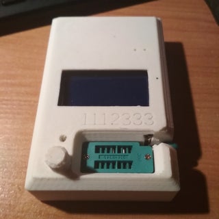
Step 1: Unpacking


 2 More Images

At this step I put some pictures to have an overview about what is this kit.
It should be mentioned that PCB is very well done and markings are very clear; so we didn't need schematic.
However I will put it here, along with manual.
Attachments

Step 2: Passive Components


Now let's get our hands dirty.
Passive components are easy to identify on PCB. But we must be careful to markings:
It's easy to make mistakes with these color-coded resistors. So it is better to identify each resistor with a multimeter/ohmmeter.
Capacitors are also easy to identify, but for some capacitors values are not printed directly (even if PCB markings corresponds exactly with component markings):
- 100nF are marked 104 (10 x 10000 pF = 100,000 pF)
- 10nF are marked 103 (10 x 1000 pF = 10,000 pF )
- 1nF are marked 1nJ (J means tolerance± 5%)
Step 3: Semiconductors


We observe that semiconductors are not exactly the same with those in the original project (from www.mikrocontroller.net):
- S9014 instead BC547
- S9012 instead BC557
- TL431 instead of LT1004
- HT7550 instead 78L05
I attach datasheets for these components (just in case).
Step 4: Sockets

Sockets and one rotary encoder.
Step 5: Battery Connector


... and spacers for LCD mounting.
Almost done.
Step 6: Display


Display module is a 128x64 pixels LCD with ST7565 controller.
Another mention worth doing at this step:
I already experience how to use this module (and ST7565 controller) in other projects; to see what libraries (Arduino and non-Arduino) are ready to use. And to get an idea (generally) about this family of LCD controllers.
I intend to test and study these libraries:
https://github.com/adafruit/ST7565-LCD "There are two 'versions' of the LCD library - one is straightup avr-gcc and the other is an Arduino Library. They're essentially the same." -from readme
https://github.com/thaletterb/ST7565R_AVR328P_Libraryuses parallel mode ... I think it can be adapted to work in serial mode.
https://github.com/svn2github/transistortesterGitHub clone of SVN repo svn://mikrocontroller.net/transistortester/
Step 7: Done

Now the tester it's ready and manual recommended to go through some steps to calibrate.
I will not go into details with with this procedure that is well presented in AVR Transistor Tester 128x64.pdf attached to this step (pages 4 - 6). Anyway it is good to keep handy the two objects that can be seen in Figure 2:
- The twisted wire is made to connect all three test ports toghether.
- 220nF capacitor used in calibration is already included in the kit.
It is important to note:
Components that could be measured are not only transistors !!!
Resistors, capacitors, potentiometers, inductors, diodes, LEDs, BJT transistors, FET transistors, thyristors, and more...
Why do I find it so important? Because studying how to measure the characteristics of these components (and this because though this project is open source) we can learn in depth about electronics in general :)
Step 8: One Step Further


Therefore this kit is not "true open-source" (i.e. we do not have design files for PCB, or exact source code for firmware); Because is so close to original project, we can use it as open source, we can modify firmware, learn and hack. And we can benefit from the low cost of mass-product kit.
So I put a short extract from CheckPins.c as an appetizer ... also a selection from schematic where all the magic is done.
Full source code (and other goodies) here:
- GitHub clone of SVN repo : https://github.com/svn2github/transistortester
- and original SVN repo: svn://mikrocontroller.net/transistortester/
From here I have two(three) directions that I'll follow:
- I will try to compile a version that fits exactly this hardware;
- I will try to experiment with stand-alone (generic and/or home-made hardware), to test and study in depth the techniques used in this project;
- And yes .. I will use this kit also to test some components... :)
I hope you liked it.
5 People Made This Project!
 PiotrP57 made it!
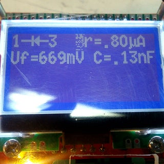 mario59 made it!
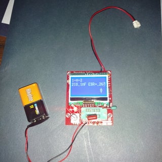 Rhuebarb made it!
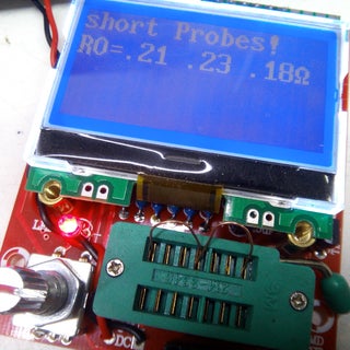 rfeigenblatt made it!
See 1 More


Recommendations


Battery Powered Contest

Plastic Contest

Make it Real Student Design Challenge


We have a be nice policy.
Please be positive and constructive.
14 Discussions
2 months ago
How to program of mega 8
2 years ago
Silvius, thank you very much for the article.
Please, can someone tell me if this kit (the one in your article) comes with Karl-Heinz Kübbeler firmware in the Atmega? Or it comes with Markus Frejek firmware and you have to reprogram the Atmega to use Karl-Heinz improvements?
I bought a version with v1.13k in it; the small yellow PCB with all SMD components, but it's broken. I assume the "k" in the version name means that it's Karl-Heinz's, am I right?
So now I plan to buy this DIY version (the one in your article) and use better components in it where it worths (680R and 470k resistors, better capacitors, etc) but would like to be sure about firmware.
Also, can I get somewhere an ATmega328 chip with current Karl-Heinz firmware in it?
Thank you in advance! Fer
Reply 2 years ago
The kit comes with a modified(chinese) early version of Karl-Heinz Kübbeler firmware. A version that has been adapted for the graphical display, because at first the tester was designed to work with a 16x2 lcd display... I guess..
However, the sources are not public, and the chip was read-protected, so I totally dropped the kit original firmware and flash one frome here:
https://github.com/svn2github/transistortester/tre...
It's been a few years since I worked on this project and I do not remember exactly which version I used. If you encounter difficulties I can read the firmware directly from the functional device and send it to you.
Regards!
Reply 2 years ago
Thank you very much for the clarification Silvius, I appreciate it.
I can't burn firmware, so I must find someone that can do it for me and send me the chip
Reply 2 years ago
I sent a private message to you... It is mega328_st7565_kit ... but I can't attach zip files here.
Reply 2 years ago
Hm... I manage to attach a zip file as an image but I don't know if will work in the end...
Reply 2 years ago
Thank you!
The file "mega328_st7565_kit.txt" is empty
The rest of files seem OK, sizes:
"fuses.txt" 46 bytes
"Makefile" 21 KB
"TransistorTester.eep" 2 KB
"TransistorTester.hex" 85 KB
"ttester.pdf" 3,3 MB
(No private message though)
Reply 2 years ago
mega328_st7565_kit.txt is only a sort of note to me... to remember what firmware I used. :)
Reply 2 years ago
Silvius, one more question: which is the last firmware version for this PCB/kit?
I can't see it at the list in the directory you gave me; I can't identify PCB/display name of it and to which version is related.
I'd like to be sure that a current version of the firmware for this PCB is still being updated... but can't see it by myself...
Thanks again!
Reply 2 years ago
I assume last/current version is 1.13k , am I right?
3 years ago
dear all I also made it but it power up only when i press the button and led is always off. Anyone solved it ? Thanks in advance v
Reply 3 years ago
:) It is supposed to work in this way.
Step1: Put electronic component in test socket. The tester is off but is connected to 9V battery.
Step2: Press button (short press). The tester back to life and makes his magic... and display the result.
Step3: If you do not test any other component... it stops after little time ... to protect battery.
About LED... If all the others functions are correct, and LED is the only thing that works incorrectly... I guess that is soldered in reverse... or defective.
Regards!
3 years ago
HI thank you for nice post
I just made it but it power up only when I press the rotary switch once I release it will power down what is the problem how can I fix it Please help I am new to this gadget
Thank you all
4 years ago
Hi, there is newer version with ATmega inputs protection (SRV05) what is sold with many names (90% names is bad).
It can be exchanged 8MHz crystal for 16MHz for other options...
http://rodi.sk/misc/avr-component-tester/