The STM32 F1-series was the first group of STM32 microcontrollers based on the
ARM Cortex-M3 core and considered their mainstream ARM microcontrollers. The F1-series has evolved over time by increasing CPU speed, size of internal memory, variety of peripherals.
There are five F1 lines: Connectivity (STM32F105/107), Performance (STM32F103), USB Access (STM32F102), Access (STM32F101), Value (STM32F100).
In this post we shall explore the ways to implement Arduino core on to STM32 so that programming can be done through Arduino IDE itself.You can enjoy the speed of 32 bit microcontroller with ease of Arduino IDE programming.
STM32 is a 72 MHz processor. The full part number STM32F103C8T6 decodes to
C8 = 128 KB flash, 20 KB RAM, 48-pin LQFP:
STM32 F1xx development boards are available in wide range.Here we shall use a simple board which is also called BLUEPILL . A very efficient & economy module easily available.
Programming can be done in many ways.This post is related to using Arduino core.
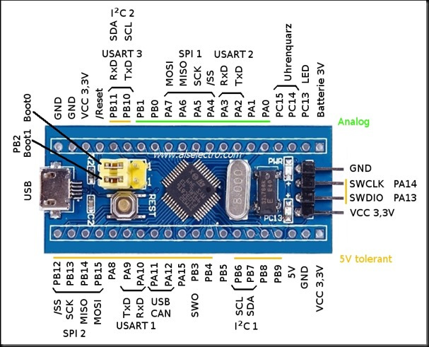
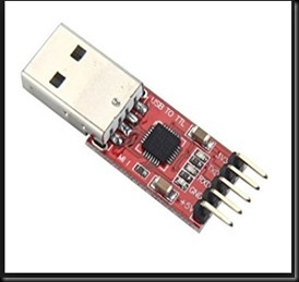
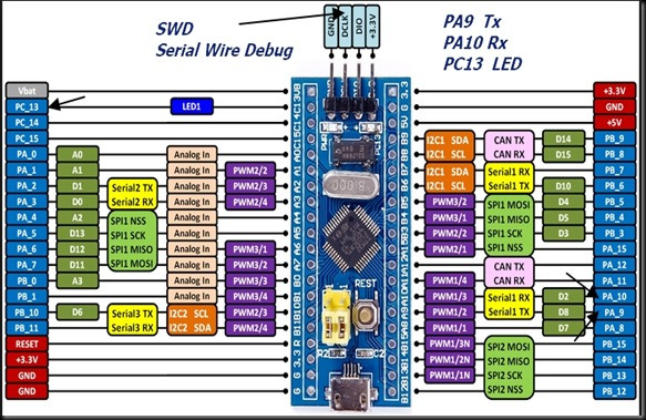
As seen in above picture , STM32 pill has 3 UARTs of which UART1 (PA9, PA10) is used to upload code.For this you need a USB-TTL module .Although the STM32 is 3.3v device many GPIO pins (shown in yellow underline in above picture) are 5V tolerant. So you can use this USB-TTL *CP2102) module without any level shifter.
The other way to upload code is through SINGLE WIRE INTERFACE ModuleInterface (SWIM) .This uses only 2 wires SWCLK, SWDIO apart from power pins .You can see this as 4 separate header pins to the right end of module.You need a ST-LINK dongle or device to connect with the SWIM.
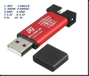
The ST-LINK/V2 is an in-circuit debugger/programmer for the STM8 and STM32 microcontrollers. The single wire interface module (SWIM) interfaces facilitate the communication with any STM8 or STM32 microcontroller operating on an application board.
The bare STM32F103 board only comes with a default USART boot loader. Even though there is a USB port on the board, you cannot use it to program it because it does not have the relevant bootloader.
In the next post we shall see how to upload using USB.
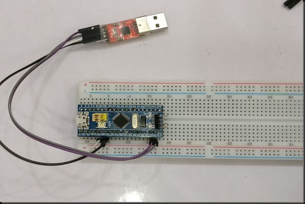
For now connect the USB-TTL module to STM32 .
PA9 TX —-> Rx of USB-TTL
PA10 RX —-> Tx of USB-TTL
5V —> 5V
GND —> GND
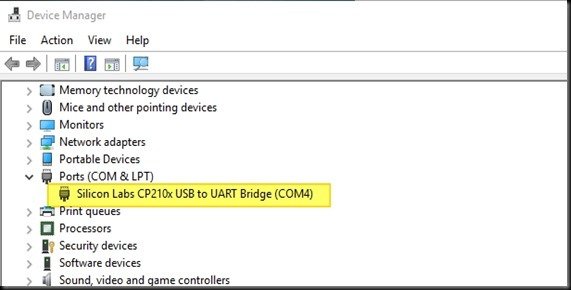
Plug in the USB-TTL module to USB of PC. CP2102 device driver is required so that PC allots a port number to the module.
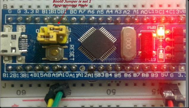
You can see 2 yellow jumpers on board.The bottom one is BOOT 1 & the top one is BOOT 0.
For programming you need to shift the BOOT 0 jumper to make High as shown in photo below.
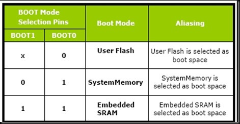
The setting of Jumpers specify the source of code for the STM32.
In the default state of both being 0, the micro-controller uses its own flash memory bootloader (factory setting is none , there is no bootloader in fresh boards)
To program the micro using USART, you need to set BOOT0 as 1 and leave BOOT1 to 0. Move the first jumper and leave the second one.
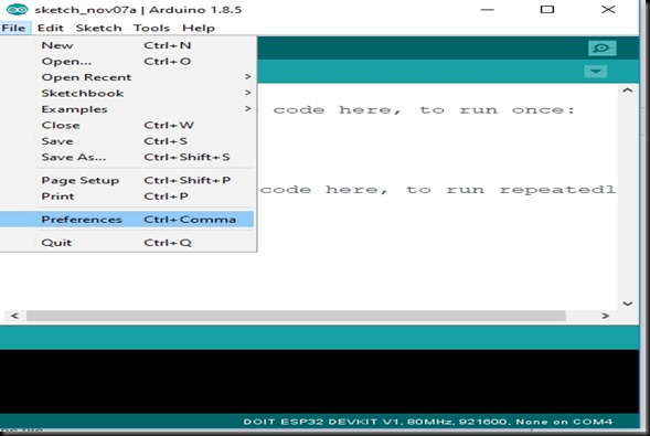
Open the Arduino IDE .
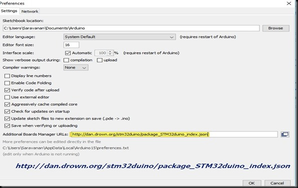
Go to File –> Preferences
At the bottom of the preferences screen , copy & paste the following link
http://dan.drown.org/stm32duino/package_STM32duino_index.json
If you have some other link already here ( for e.g you might have installed for NodeMCU) , put a comma after the existing one & then paste the link
Click OK.
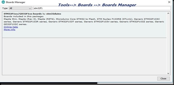
Now under Tools —> Boards select Boards Manager
Internet connection is required to install board support chain link.
Type in STM32F1 & select STM32F1xx boards by stm32duino.
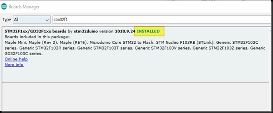
Select the latest version & click install.
It takes some time to get installed.
Now reopen the ARDUINO IDE.
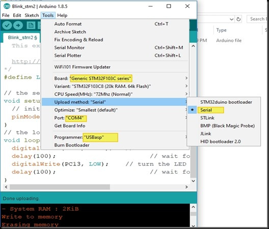
Under Tools make the following settings:
Board : Generic STM32F103C Series
Variant : 20k ram 64k flash
Very important is Upload method which is SERIAL
Port : port no. alloted to USB-TTL
Progemmer : USBasp
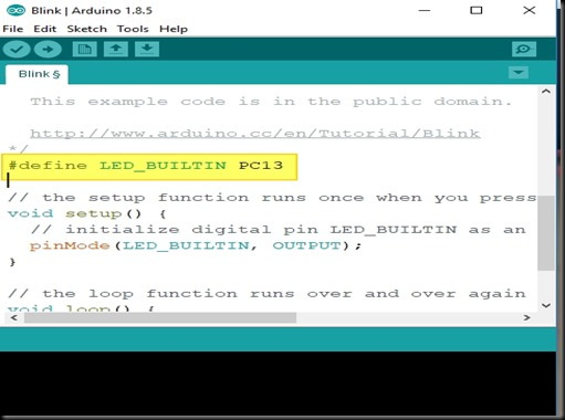
Open the Blink sketch
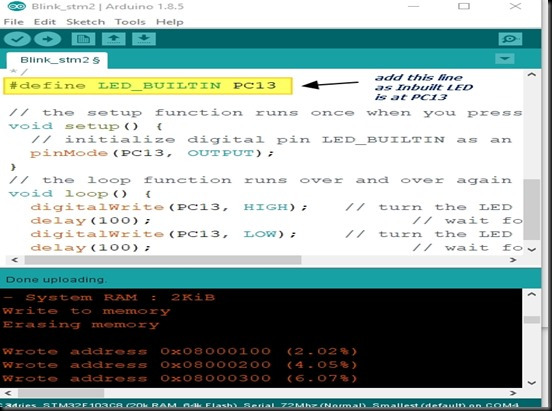
Add this before void setup
#define LED_BUILTIN PC13
Save the file.
As seen in picture below , the built in LED on STM32 bluepill is mapped to PC13
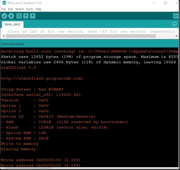
Click on Upload
Once the code is uploaded you can see the built in LED blinking accordingly.Now you can reset the BOOT 0 jumper back to 0 position & press Reset to start the freshly uploaded code.
For next upload you need to set the BOOT 0 to position 1 & press Reset button.
Let us see the second method to upload code through SWIM.
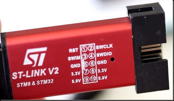
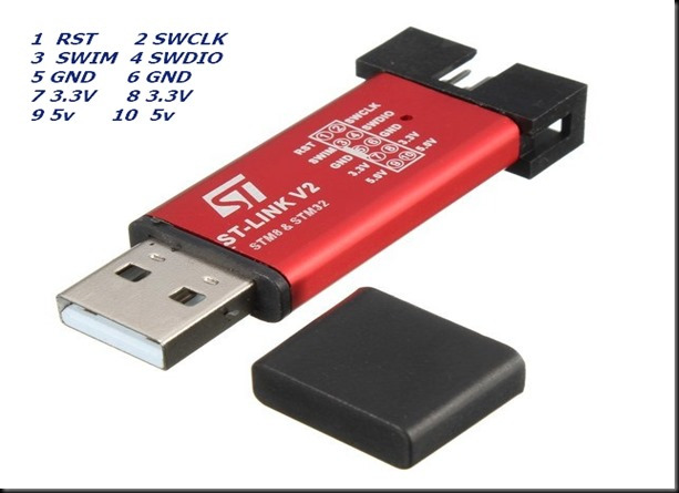
For this you need a ST LINK V2 dongle as shown in picture below :
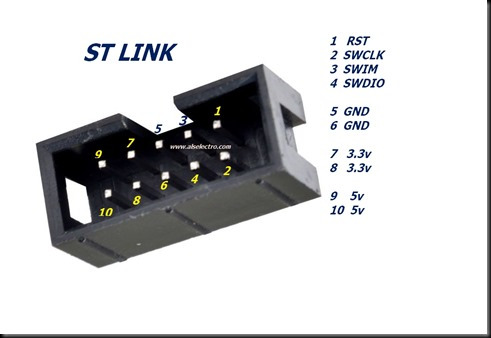
The pin details of STLINK is printed on the module itself.
Pin number starts from top , as shown below
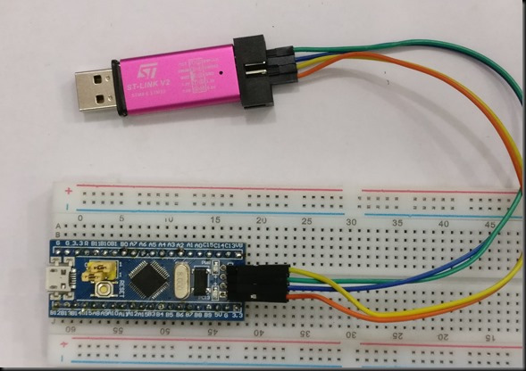
Connect STLINK to STM32 as below :
Pin2 SWCLK —> DCLK of STM32
Pin4 SWDIO —> DIO of STM32
Pin6 GND –> GND
Pin 8 3.3V –> 3,3V
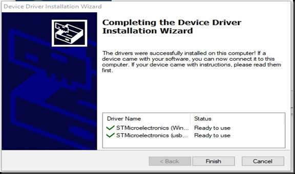
Before connecting ST LINK to PC , download & install the driver from below link
https://www.st.com/en/development-tools/stsw-link009.html
This USB driver (STSW-LINK009) is for ST-LINK/V2 and ST-LINK/V2-1 boards and derivatives (STM32 discovery boards, STM32 evaluation boards, STM32 Nucleo boards)
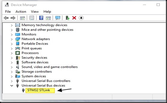
Once the drivers are installed you see under Device Manager – > Universal Serial Bus Device
STM32 ST Link
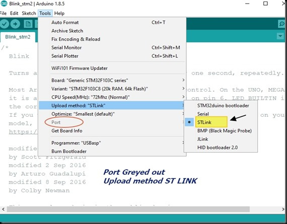
Open the Arduino IDE
Select board as STM32F103C Series
Upload method to be selected as ST Link
Port will be greyed out ,as No selection of port required
Note that there is no need to shift Jumper in this method of uploading.
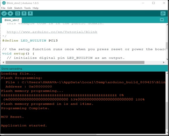
Just click on upload to see the inbuilt LED blinking.
VIDEO DEMO:



Good Work bro , But industry will move on ARM Cortex-M4 , so in future will u pls Post reagrding Cortex M4 series will welcoming …it will helpful for many students , Professionals and Enthusiastic
Please correct your statement: “Let us see the second method to upload code through SWIM.”
– It should read: Let us see the second method to upload code through SWD.!!!
The instructions are great and easy to follow. But when I went to upload from Arduino, it just printed errors. I’m guessing there is no bootloader, but really have no idea why. Can you offer some debugging ideas when upload fails? I’m using OSX so maybe the software doesn’t do that, the messages seem to indicate so:
Error probing interface “serial_posix”
stm32flash Arduino_STM32_0.9
Cannot handle device “/dev/cu.usbserial-A602HTIL”
Failed to open port: /dev/cu.usbserial-A602HTIL
http://github.com/rogerclarkmelbourne/arduino_stm32
Using Parser : Raw BINARY
the selected serial port
does not exist or your board is not connected
Thank you for outlining the required steps in a clear and precise manner. Other tutorials I looked at seemed to miss steps or assume knowledge but this tutorial was precise and after following it I was able to program the STM32F103 board for the first time using serial and a FTDI UART.