Introduction: Arduino CAP-ESR-FREQ Meter


CAP-ESR-FREQ meter with an Arduino Duemilanove.
In this instructable you can find all neccessary information about a metering instrument based on an Arduino Duemilanove. With this instrument you can measure three things: capacitor values in nanofarads and microfarads, the equivalent serie resistance (ESR value) of a capacitor and last but not least frequencies between 1 Herz an 3 MegaHerz. All three designs are based upon descriptions I found on the Arduino forum and on Hackerstore. After adding some updates I combined them into one instrument, controlled with just one Arduino ino program. The different meters are selected via a three position selector switch S2, connected to pins A1, A2 and A3. ESR zeroing and meter selection reset is done via a single pushbutton S3 on A4. Switch S1 is the power ON/OFF switch, needed for 9 V DC battery power when the meter is not connected to a PC via USB.
These pins are used for input:
A0: esr value input.
A5: capacitor input.
D5: frequency input.
The meter uses a Liquid Crystal Display (LCD) based on the Hitachi HD44780 (or a compatible) chipset, which is found on most text-based LCDs. The library works in 4- bit mode (i.e. using 4 data lines in addition to the rs, enable, and rw control lines). I started this project with an lcd with only 2 datalines the (SDA and SCL I2C connections) but unfortunally this conflicted with the other software I used for the meters. First I will explain he three different meters and finally the assembly instructions. With each type of meter you can also download the separate Arduino ino file, if you want to only install that specific type of meter.
Attachments


Step 1: The Capacitor Meter

The digital capacitor meter is based on a design from Hackerstore.
Measuring the value of a capacitor:
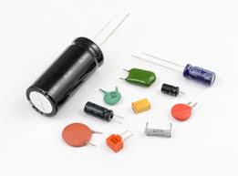
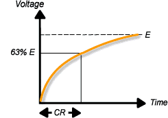
Capacitance is a measure of the ability of a capacitor to store electrical charge. The Arduino meter relies on the same basic property of capacitors: the time constant. This time constant is defined as the time it takes for the voltage across the capacitor to reach 63.2% of its voltage when fully charged. An Arduino can measure capacitance because the time a capacitor takes to charge is directly related to its capacitance by the equation TC = R x C. TC is the time constant of the capacitor (in seconds). R is the resistance of the circuit (in Ohms). C is the capacitance of the capacitor (in Farads). The formula to get the capacitance value in Farads is C = TC/R.
In this meter the R value can be set for calibration between 15kOhm and 25 kOhm via potmeter P1. The capacitor is charged via pin D12 and discharged for a next metering via pin D7. The charged voltage value is measured via pin A5. The full analog value on this pin is 1023, so 63.2% is represented by a value of 647. When this value is reached, the program calculates the capacitor value based on the above mentioned formula.
Attachments
Step 2: The ESR Meter

See for definition of ESR https://en.wikipedia.org/wiki/Equivalent_series_resistance.
See for the original Arduino forum topic https://forum.arduino.cc/index.php?topic=80357.0
Thanks to szmeu for the start of this topic and mikanb for his esr50_AutoRange design. I used this design including most of the comments and improvements for my esr meter design.
Equivalent Series Resistance (ESR) is the internal resistance that appears in series with the device's capacitance. It can be used to find faulty capacitors during repair sessions. No capacitor is perfect and the ESR comes from the resistance of the leads, the aluminium foil and the electrolyte. It is often an important parameter in power supply design where the ESR of an output capacitor can affect the stability of the regulator (ie, causing it to oscillate or over react to transients in the load). It is one of the non-ideal characteristics of a capacitor which may cause a variety of performance issues in electronic circuits. A high ESR value degrades the performance due to power losses, noise, and a higher voltage drop.
During the test, a known current is passed through the capacitor for a very short time so the capacitor doesn’t charge completely. The current produces a voltage across the capacitor. This voltage will be the product of the current and the ESR of the capacitor plus a negligible voltage due to the small charge in the capacitor. Since the current is known, the ESR value is calculated by dividing the measured voltage by the current. The results are then displayed on the meter display. The test currents are generated via transistors Q1 and Q2, their values are 5mA (high range setting) and 50mA, (low range setting) via R4 and R6. Discharching is done via transistor Q3. The capacitor voltage is measured via analog input A0.
Attachments
Step 3: The Frequency Meter

See for the original data the Arduino forum:
https://forum.arduino.cc/index.php?topic=324796.0#main_content_section.
Thanks to arduinoaleman for his great frequency meter design.
The frequency counter works as follows:
The 16bit Timer/Counter1 will add up all clocks coming in from pin D5. Timer/Counter2 will generate an interrupt every millisecond (1000 times per second). If there is an overflow in Timer/Counter1, the overflow_counter will be increased by one. After 1000 interrupts (= exactly one second) the number of overflows will be multiplied by 65536 (this is when the counter flows over). In cycle 1000 the current value of the counter will be added, giving you the total number of clock ticks that came in during the last second. And this is equivalent of the frequency you wanted to measure (frequency = clocks per second). The procedure measurement(1000) will set up the counters and initialise them. After that a WHILE loop will wait until the interrupt servive routine sets measurement_ready to TRUE. This is exactly after 1 second (1000ms or 1000 interrupts). For hobbyists this frequency counter works very well (apart from lower frequencies you can get 4 or 5 digit accuracy). Especially with higher frequencies the counter gets very acurate. I have decided to display only 4 digits. However, you can adjust that in the LCD output section. You must use D5 pin of the Arduino as the frequency input. This is a prerequirement for using the 16bit Timer/Counter1 of the ATmega chip. (please check the Arduino pin for other boards). To measure analog signals or low-voltage signals a preamplifier is added with a pre-amplifier transistor BC547 and a block pulse shaper (Schmitt trigger) with a 74HC14N IC.
Attachments
Step 4: The Components Assembly


 6 More Images


The ESR and CAP circuits are mounted on a piece of perfboard with holes 0.1 inch distance. The FREQ circuit is mounted on a separate perfboard (this circuit was added later). For the wired connections male headers are used. The lcd screen is mounted in the top cover of the box, together with the ON/OFF switch. (And one spare switch for future updates). The layout was made on paper (much easier than using Fritzing or other design programs). This paper layout was later also used to check the real circuit.
Step 5: The Box Assembly


 5 More Images


A black plastic box (dimensions WxDxH 120x120x60 mm) was used to mount all components and both circuit boards. The Arduino, the perfboard circuits and the battery holder are mounted on a 6mm wooden mounting plate for easy assembly and soldering. In this way everything can be assembled and when finished it can be placed inside the box.
Under the circuit boards and the Arduino nylon spacers were used to prevend the boards from bending.
Step 6: The Final Wiring


Finally all internal wired connections are soldered. When this was completed, I tested the esr switching transistors, via the test connections T1, T2 and T3 in the wiring diagram. I wrote a small test program to change the connected outputs D8, D9 and D10 from HIGH to LOW every second and checked this on the connections T1, T2 and T3 with an oscilloscope.
To connect the capacitors under test a pair of short test wires were made with crocodile clip connections.
For frequency metering longer test wires can be used.
Happy testing!
Be the First to Share
Recommendations


Battery Powered Contest

Plastic Contest
Block Code Contest


We have a be nice policy.
Please be positive and constructive.
4 Discussions
Question 2 months ago
thanks a lot for the project. I'm missing a part list to be sure of every component specification (sorry I'm quite a newbie). Is it possible to add it? Thanks again
Answer 2 months ago
Hi Matteobauz,
I have added a parts list on the first page.
Alex
Reply 2 months ago
that's great! I still cannot see it on the first page. Do it need some approval from Instructables before publishing? Or is it just because is late and I should go to bed? :)
Reply 2 months ago
Hi Matteobauz,
You must clear the cache of your browser, then you will see the updated instructables page.