Introduction: Micro SD Card Tutorial


Description
This Micro SD Card is used for transfering data to and from a standard sd card. The pin out is directly compatible with Arduino and also can be used with other microcontrollers. It allow us to add mass storage and data logging to our project.
Features
- Input Voltage: 3.3V/5V
- With all SD SPI Pins out :MOSI, SCK, MISO and CS ,for further connection
- Through programming, you can read and write to the SD card using your arduino
- Make your SD application more easier and simple
- Communicate with Arduino using SPI interface
- Push-pop socket with card slightly over the edge of the PCB so its easy to insert and remove
- 4 mounting holes with 2.2mm diameter
- Only use 4 I/O pins on the Arduino
- Size: 42mm x 25mm x 5mm
Supplies
Step 1: Step 1 : Material Planning


For this tutorial, the items needed to run this project are:
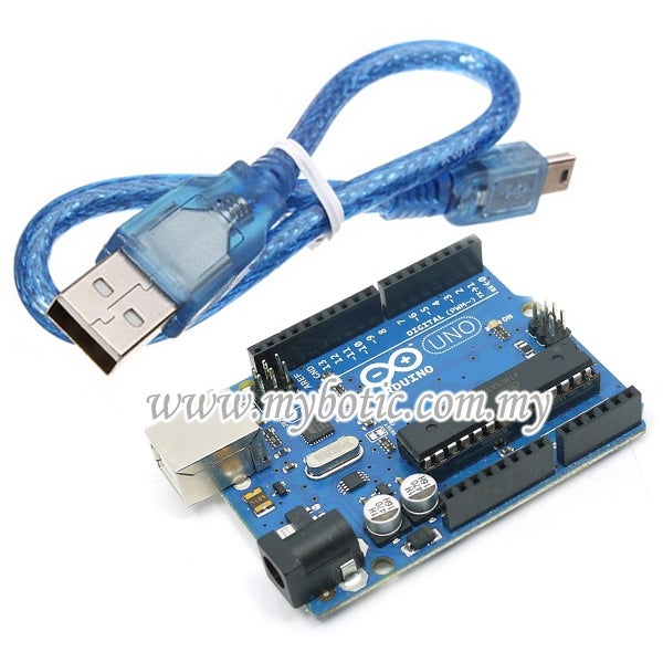
- Arduino Uno
- USB Cable type A to B
- Micro Sd Card Module
- Female to male jumper wire
- SD Card
Step 2: Step 2 : Hardware Installation


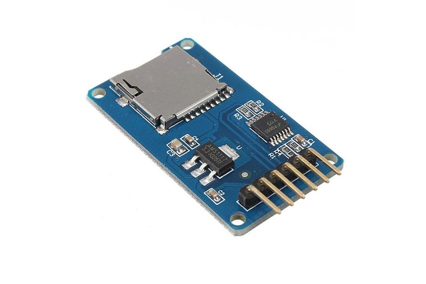
Micro SD Card Module
This module uses the standard SPI interface for communication, which involve SPI buses, MISO, MOSI, SCK, and a CS signal pin. through programming, the data can easily be read and wrote into SD Card by using the Arduino or other microcontrollers.
- CS (chip select)
- SCK (serial clock)
- MOSI (master out slave in)
- VCC (3.3V or 5V)
- GND (ground)
Diagram above shows the simple connection between Micro SD Card Module and Arduino UNO:
- Connect VCC with 5V in the Arduino.
- Then, connect the GND of SD card to the ground of Arduino.
- Connect CS to pin 14
- Connect SCK to pin 13
- MOSI connect to the pin 11
- Lastly, connect MISO to pin 12
After completing the connection, connect the Arduino to power supply with USB cable.
Step 3: Step 3: Insert Coding
Lets try an example in the Arduino.
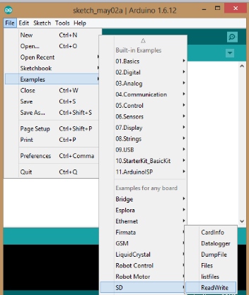
- Open the Arduino software
- Click 'file'
- Find the 'example'
- Click 'SD'
- Choose 'ReadWrite'
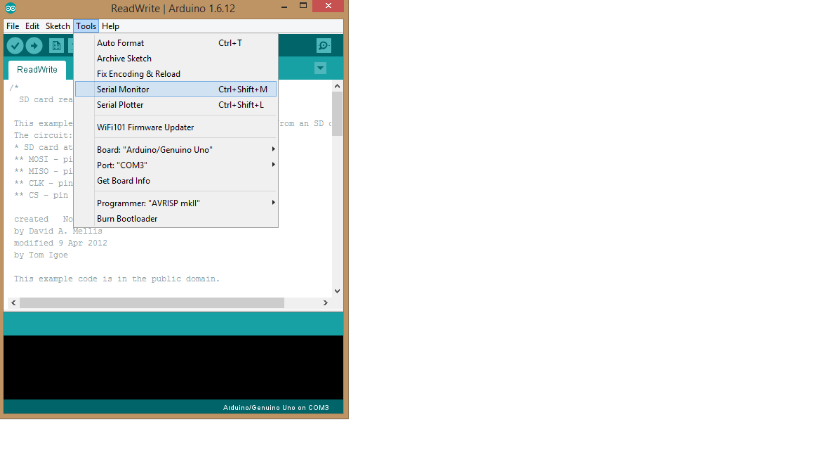
Step 4: Step 4 : Choose COM Port
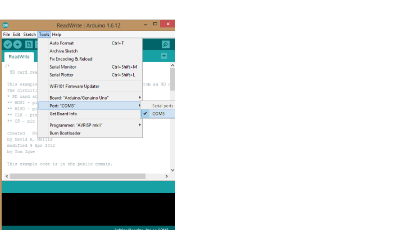
Just click at 'Tools', then choose your port available on your PC.
Step 5: Step 5 : Upload Souce Code
Upload the source code into the Arduino and open the Serial Monitor to se the result.
Step 6: Ster 6 : Result
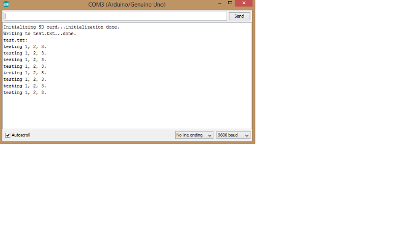
The following result will be displayed in the monitor. In this example, the .txt file named "test.txt" was created and the sentence "testing 1,2,3." were wrote into the .txt file. After this, the sentence "testing 1,2,3." were read back from .txt file and display on serial monitor.
4 People Made This Project!


Recommendations


Toys & Games Contest

Organizers: Student Design Challenge
Fix It Challenge


We have a be nice policy.
Please be positive and constructive.
24 Comments
4 months ago
6 months ago
Reply 5 months ago
7 months ago
Question 10 months ago
Tip a year ago
In this example the Arduino Uno board is used. If you have another board please take a look at what pin setup your specific board is using.
From the text above, the SD card CS (Chip Select) is pointed out to be wired to pin 14 at the Arduino. In the figure however the yellow wire goes to pin 4. Also in the code the SD.begin() is using the pin 4 as argument. So this is a typo (well, actually it is the pin 14 on the ATMEGA328 MCU chip which is connected to pin 10 on Uno) - connect to pin 4 to get it to work with the example code.
It often directs the CS to pin 4 in different demos, i don't know why.
If you take a read in the reference of the SD [https://www.arduino.cc/en/reference/SD] it tells you that the Arduino pin 10 as a standard pin for CS [ SD.begin(CSPIN) ] and in the case that you decide to use standard pin (10) you will not need to specify the pin as an argument, and makes this setup to use the Arduino pins 10 through 13. This is useful as to keeping the wires together. Quite often if you would like to use LCD, or what ever, the pin 4 is then used by that or other setups.
This specific SD Card breakout is using a 5v to 3.3V voltage regulator (U) so you don't need to worry about burning/destroying the card from a standard 5V Arduino system. Also the other U1 marked chip on the PCB (Printed Circuit Board) is a level converter that keeps the 5V on one side and 3.3V on the other side. All the interface memory logic's is taken care of by the memory card. So if you would have a pure 3.3V Arduino system those chip would not be really needed, and you could look for a less complex SD card reader. But this break out card works in both 5V and 3.3V setups, so you wouldn't need more than one break out if you are trying both type of Arduino boards.
For further details see also: https://www.arduino.cc/en/Reference/SDCardNotes
I hope that you will have much joy of the SD card storing and reading.
And one final thing - allways(!) format all your SD cards with "SD Card Formatter" from SD Assosiation. [https://www.sdcard.org/downloads/formatter/]
Question 2 years ago
Question 2 years ago
2 years ago
http://bigbelectronics.in/product.php?product=micro-sd-tf-card-memory-shield-module-spi-micro-sd-storage-expansion-board-arduino
2 years ago
Can you please help me!
Thanks in advance...
2 years ago
Question 2 years ago
3 years ago
I'm getting the "initialization failed!" error and wondering what's not correct. Can anyone explain this code?
if (!SD.begin(4)) {
Serial.println("initialization failed!");
return;
}
Reply 3 years ago
Got it! For an Arduino Mega, we want to use pins 50, 51, 52, and 53 for MISO, MOSI, SCK, and CS, respectively.
Reply 3 years ago
Reply 2 years ago
I'm having the same error.
Reply 2 years ago
Question 2 years ago
for example :(Nano V3.0 ATmega328P CH340G 5V 16M micro-controller Arduino
Micro SD TF Memory Card Reader Module with SPI interface For Arduino PI Portable)
3 years ago
Nice,
I notice CS is to be plugged in pin4 as drawn. But you wrote 'Connect CS to pin 14'
Best regards
Reply 2 years ago
Question 3 years ago
Arduino: 1.8.5 (Windows 10), Board: "Arduino/Genuino Uno"
Sketch uses 11132 bytes (34%) of program storage space. Maximum is 32256 bytes.
Global variables use 1026 bytes (50%) of dynamic memory, leaving 1022 bytes for local variables. Maximum is 2048 bytes.
avrdude: stk500_getsync() attempt 1 of 10: not in sync: resp=0x30
avrdude: stk500_getsync() attempt 2 of 10: not in sync: resp=0x20
avrdude: stk500_getsync() attempt 3 of 10: not in sync: resp=0x30
avrdude: stk500_getsync() attempt 4 of 10: not in sync: resp=0x20
avrdude: stk500_getsync() attempt 5 of 10: not in sync: resp=0x30
avrdude: stk500_getsync() attempt 6 of 10: not in sync: resp=0x20
avrdude: stk500_getsync() attempt 7 of 10: not in sync: resp=0x30
avrdude: stk500_getsync() attempt 8 of 10: not in sync: resp=0x20
avrdude: stk500_getsync() attempt 9 of 10: not in sync: resp=0x30
avrdude: stk500_getsync() attempt 10 of 10: not in sync: resp=0x20
An error occurred while uploading the sketch
This report would have more information with
"Show verbose output during compilation"
option enabled in File -> Preferences.
Answer 3 years ago
update board drivers . then re connect the board. select the correct port and upload your file
Question 3 years ago on Step 6
I am using the same process..
but it shows "sd fail" or "fail to initialize sd card"
how can i resolve this?
Answer 3 years ago
Try using 5V instead of 3.3V, that solved it for me.
Also, format the SD card to FAT or FAT32 before using it with the module.