_ztBMuBhMHo.jpg) |
| × | 1 | |||
| × | 2 | ||||
 |
| × | 2 | |||
 |
| × | 2 | |||
 |
| × | 2 | |||
 |
| × | 2 | |||
 |
| × | 1 | |||
 |
| × | 1 |
.png)
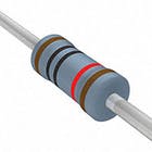
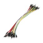
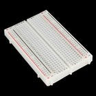
Components and supplies
Apps and online services

About this project
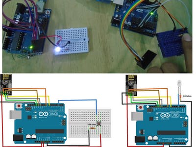
In this tutorial, you will learn about nRF24L01 Arduino interfacing with the help of two examples. In the first example, we will send “Hello world” and a command to blink the LED connected to the other Arduino. In the second example, we will do the bidirectional control and will send the command from First Arduino to blink the LED on the second and then we will send the command from second Arduino to blink the LED on the first.
For Custom Projects, hire me at https://www.freelancer.com/u/Muhammadaqibdutt
Before going in detail, first have a look at the specification of this module
nRF24L01 ModuleThe nFR24L01 is a transceiver module which means that it can both send and receive the data.
These modules are very cheap, smaller in size and has a lot of specifications. Some of the specifications of these modules are as follows
Specifications of nRF24L01 Module- Power consumption is around 12mA during transmission which is even lesser than the led.
- It can operate with baud rates from 250Kbps up to 2 Mbps.
- Its range can reach up to 100 meters if used in open space and with antenna.
- It can both send and receive the data simultaneously.
- Each module can communicate with up to 6 other modules.
- It uses the 2.4 GHz band.
- It can send 1 to 25 bytes of raw data at the transmission rate of 1 MB.
- It has 125 different channels.
The nRF24L01 module works with the Arduino through the SPI communication. The pinout of the module is as follows
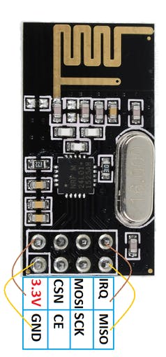
The operating voltage of this module is from 1.9 to 3.6V but the other pins are 5V tolerant which means that the other pins can be directly connected to the Arduino.
The MOSI, MISO and the SCK are the SPI pins and these needs to be connected to the SPI pins of Arduino. Different Arduino’s have different SPI pins.
The CSN and CE are for setting the module in active mode and for switching between command and transmit mode. These can be connected to any digital pins of Arduino.
The IRQ pin is the interrupt pin and you don’t have to connect it.
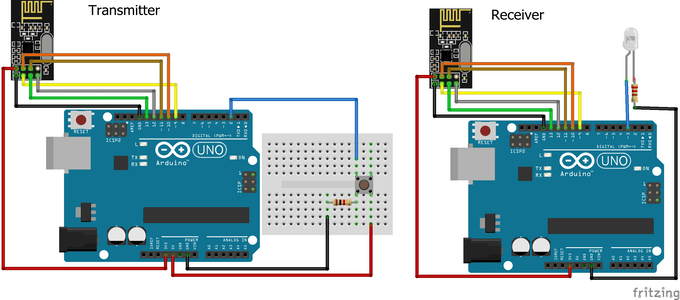
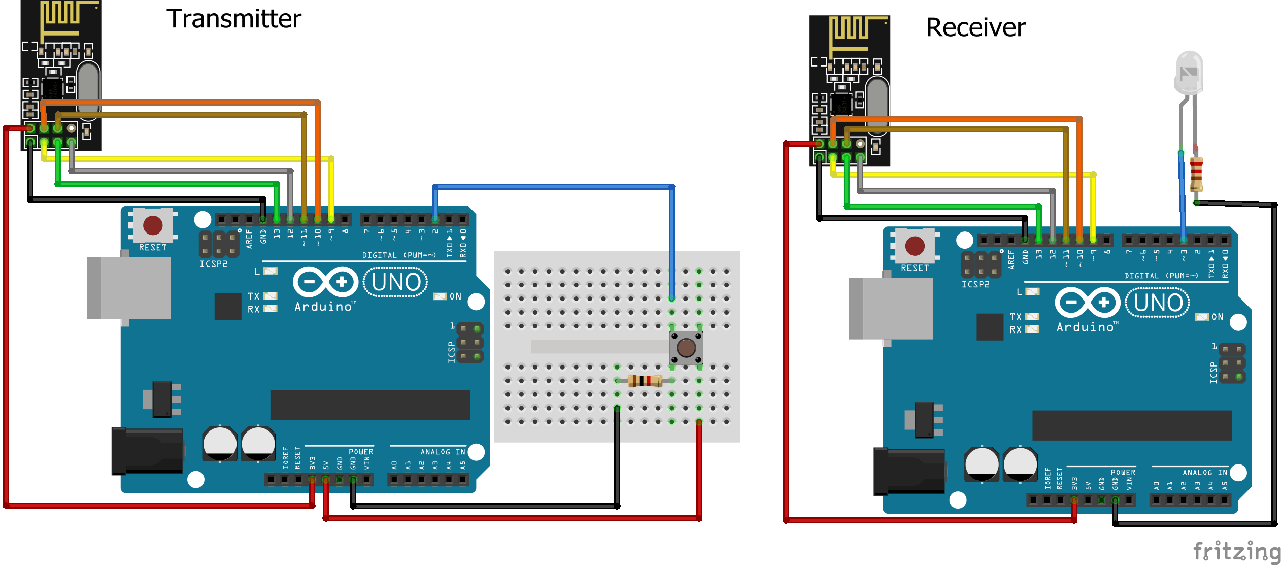
Example 1 - nRF24L01 Arduino InterfacingIn the first example for nRF24L01 arduino interfacing, we are going to simply send the data from one Arduino to other Arduino. When we will press the button connected to the first Arduino, LED connected to the second Arduino will light up.
The circuit diagram for the first example is shown below and the connections are shown below that.
Download the library from here.
#include <SPI.h>
#include <nRF24L01.h>
#include <RF24.h>
RF24 radio(9, 10); // CE, CSN
const byte address[6] = "00001";     //Byte of array representing the address. This is the address where we will send the data. This should be same on the receiving side.
int button_pin = 2;
boolean button_state = 0;
void setup() {
pinMode(button_pin, INPUT);
radio.begin();                  //Starting the Wireless communication
radio.openWritingPipe(address); //Setting the address where we will send the data
radio.setPALevel(RF24_PA_MIN);  //You can set it as minimum or maximum depending on the distance between the transmitter and receiver.
radio.stopListening();          //This sets the module as transmitter
}
void loop()
{
button_state = digitalRead(button_pin);
if(button_state == HIGH)
{
const char text[] = "Your Button State is HIGH";
radio.write(&text, sizeof(text));                  //Sending the message to receiver
}
else
{
const char text[] = "Your Button State is LOW";
radio.write(&text, sizeof(text));                  //Sending the message to receiver
}
radio.write(&button_state, sizeof(button_state));  //Sending the message to receiver
delay(1000);
}#include <SPI.h>
#include <nRF24L01.h>
#include <RF24.h>
RF24 radio(9, 10); // CE, CSN
const byte address[6] = "00001";
boolean button_state = 0;
int led_pin = 3;
void setup() {
pinMode(6, OUTPUT);
Serial.begin(9600);
radio.begin();
radio.openReadingPipe(0, address); //Setting the address at which we will receive the data
radio.setPALevel(RF24_PA_MIN); //You can set this as minimum or maximum depending on the distance between the transmitter and receiver.
radio.startListening(); //This sets the module as receiver
}
void loop()
{
if (radio.available()) //Looking for the data.
{
char text[32] = ""; //Saving the incoming data
radio.read(&text, sizeof(text)); //Reading the data
radio.read(&button_state, sizeof(button_state)); //Reading the data
if(button_state == HIGH)
{
digitalWrite(6, HIGH);
Serial.println(text);
}
else
{
digitalWrite(6, LOW);
Serial.println(text);}
}
delay(5);
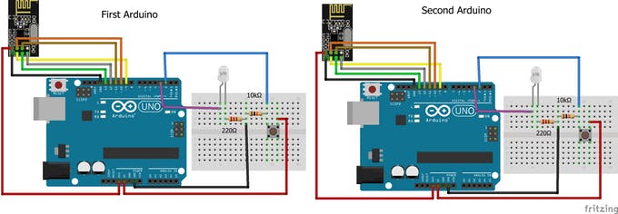
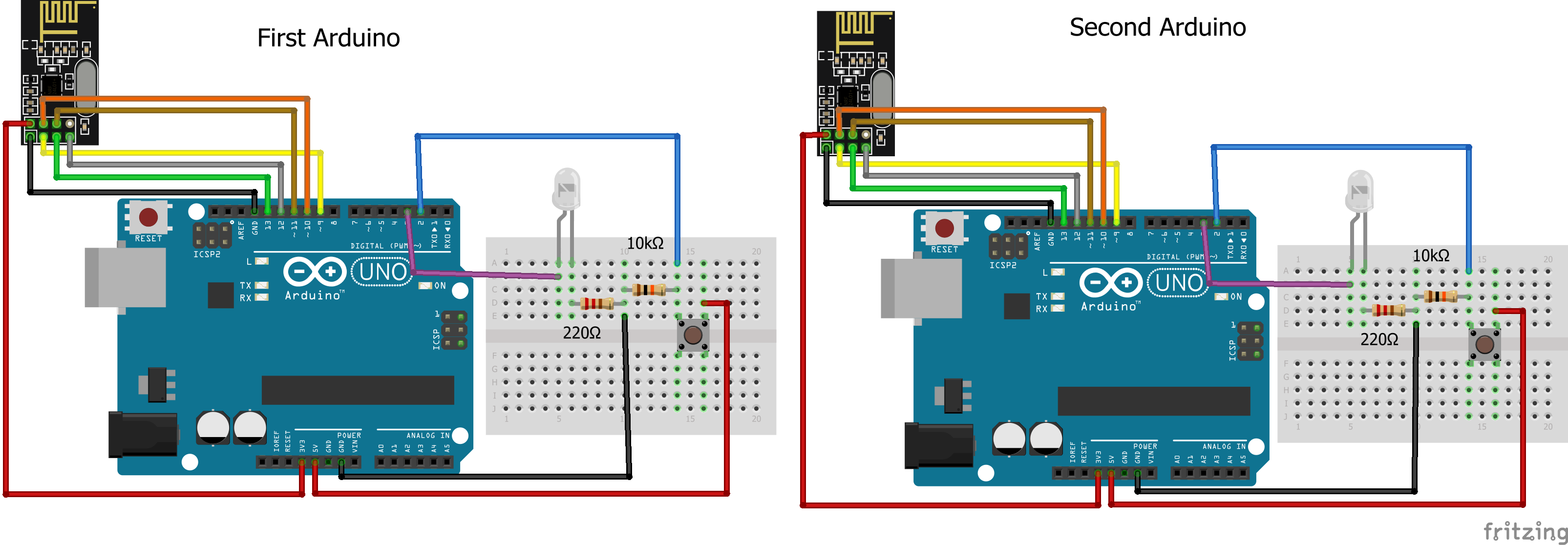
}In the second example for nRF24L01 Arduino interfacing, we are going to do the bidirectional communication. First, we will send the command from the first Arduino to light up the LED connected to the second Arduino and then we will send the command from the second Arduino to light up the LED connected to the first Arduino.
#include <SPI.h>
#include <nRF24L01.h>
#include <RF24.h>
RF24 radio(9, 10); // CE, CSN
const byte addresses [][6] = {"00001", "00002"};  //Setting the two addresses. One for transmitting and one for receiving
int button_pin = 2;
int led_pin = 3;
boolean button_state = 0;
boolean button_state1 = 0;
void setup() {
  pinMode(button_pin, INPUT);
  pinMode(led_pin, OUTPUT);
  radio.begin();                           //Starting the radio communication
  radio.openWritingPipe(addresses[1]);     //Setting the address at which we will send the data
  radio.openReadingPipe(1, addresses[0]);  //Setting the address at which we will receive the data
  radio.setPALevel(RF24_PA_MIN); //You can set it as minimum or maximum depending on the distance between the transmitter and receiver.
}
void loop()
{
  delay(5);
  radio.stopListening();                             //This sets the module as transmitter
  button_state = digitalRead(button_pin);
  radio.write(&button_state, sizeof(button_state));  //Sending the data
  delay(5);

  radio.startListening();                            //This sets the module as receiver
  while(!radio.available());                         //Looking for incoming data
  radio.read(&button_state1, sizeof(button_state1)); //Reading the data
  if (button_state1 == HIGH)
  {
    digitalWrite(led_pin, HIGH);
  }
  else
  {
    digitalWrite(led_pin, LOW);
  }
}#include <SPI.h>
#include <nRF24L01.h>
#include <RF24.h>
RF24 radio(9, 10); // CE, CSN
const byte addresses [][6] = {"00001", "00002"}; //Setting the two addresses. One for transmitting and one for receiving
int button_pin = 2;
boolean button_state = 0;
boolean button_state1 = 0;
int led_pin = 3;
void setup() {
pinMode(led_pin, OUTPUT);
Serial.begin(9600);
radio.begin(); //Starting the radio communication
radio.openWritingPipe(addresses[0]); //Setting the address at which we will send the data
radio.openReadingPipe(1, addresses[1]); //Setting the address at which we will receive the data
radio.setPALevel(RF24_PA_MIN); //You can set it as minimum or maximum depending on the distance between the transmitter and receiver.
}
void loop()
{
delay(5);
radio.startListening(); //This sets the module as receiver
if (radio.available()) //Looking for incoming data
{
radio.read(&button_state, sizeof(button_state));
if(button_state == HIGH)
{
digitalWrite(led_pin, HIGH);
}
else
{
digitalWrite(led_pin, LOW);
}
delay(5);
radio.stopListening(); //This sets the module as transmitter
button_state1 = digitalRead(button_pin);
radio.write(&button_state1, sizeof(button_state1)); //Sending the data
}
}Code
NRF24l01 Library
Schematics
Comments
Author

Published on
December 18, 2018Members who respect this project


.jpg)

and 71 others
you might like

Please log in or sign up to comment.
cedric1980
2 years agoThanks a lot for this project, just realised it !
I just have a little problem, after 1 minute or less, I loose communication between the two boards and I have to reset it. I use a breakout bord (5 v to 3,3 V) and use the 5 Vdc output of my uno boards.
Thanks
Cédric
Aqib
2 years agoTry using a different address.
Tom George
2 years agoCheck that your 5V supply is sufficient to keep the 3.3V regulated.
A trick is to put a 10uF 16V capacitor across the 3.3v at the NRL.
When it transmits it causes the current to jump, the capacitor will help supply that current increase.
.
eldeer
2 years agoit does not work
PEPONNETL
2 years agoHello; thanks to you for this tuto;
Little mistake on receiver code for the first exemple; you don't use the variable led_pin in methods PinMode() and digitalWrite().
thanks again!
Hewnikel
2 years agoThanks a lot.. however I have a weird case happening..
I am using the NRF24L for communication in a car chassis project including a car and remote control, in addition to an Ultrasonic Sensor HC - SR04 in the car for distance measurement.
the problem is when the receiver (car) has "radio.begin()" instruction in its code, the sensor doesn't work and serial keeps showing 0 distance. when I remove (or comment) the radio.begin() instruction, the sensor starts showing distance data correctly! (even though i still didn't attach the NRF24L module yet, only code is done).
has anyone faced it before??!!
elnur444
2 years agoThanks for the best information.
arehaslum
a year agoI've looked all over the web, but can't seem to find a solution for this using
Arduino Micro. I've tried using "while (!Serial);" in the setup, but can not see anything on the monitors. Does anyone have any experience using the NRF24L01 and Arduino Micro? Seems to me that this is an unsolved problem?
Pat2210
a year agoHello, I have a question about example 1. Can I plug a button on one arduin to one port while plugging an LED into the same port on the other arduin?
hermanb3
a year agoHi Mohammad,
Thank you for this information.
I am busy with a simple project to detect a switch and transmit the status to another Arduino where a relay will operate to indicate the change in status. Your example code is simple enough for me to understand as a complete newbie to Arduino programming. I do have some programming experience in Assembler.
Everything works perfectly the first time around. The only thing I picked up though is that if I open up the Serial Monitor on the Arduino the Receiver doesn't operate that well anymore.The data displayed is also not legible every time. With the monitor closed everything works fine.
I do have two questions though. Firstly, is there a way to detect if the communication fails between the two nRF24L01 modules? If there is no activity on the switch, how will I know if it still works after a day or two? I would like to maybe have a slow flashing LED on the receiver to indicate that the communication is still going. Secondly, is it possible to transmit only when the switch closes to save on battery power? (I will be using a small battery for the transmitter).
Keep up the good work.
Nartarox
a year agoHello, I tested the program "an arduino transmitter and an arduino receiver" with NANO arduinos, it doesn't work. So I would like to know:
How do I know that the NRF24 modules work?
How do I know that the module actually sends data?
How do I know if the module is receiving?
Fowelld
10 months agoHello, I have also tested the program "an arduino transmitter and an arduino receiver" with NANO arduinos, it doesn't work I have also tested the programs with Arduino UNO's and could not get them to work. I have tried with different RNF24L01's and got the same result So I would like to know:
How do I know that the NRF24 modules work?
How do I know that the module actually sends data?
How do I know if the module is receiving?
alanmjsundo
9 months agoit works, just put the RX input to Pin 6 or change the code to Pin2(Pin 6 is written)
Maddy Sharma
8 months agoit still not works need help
lightthedreams
9 months agothank you for a good tutorial. it works but after some modification refer to the previous comment about the variable on the output pin. i have one question why i got my data transmitted seems like little bit lag/delay when i push the button and the led is on. any advise?
lightthedreams
9 months agoit's now ok for the 1 way communication is working properly. thank you
now, i am trying to make the 2 ways communication. 1-2 times are ok, but later there comes problem seems like there is crash between the program. could you advise me? thanks
lightthedreams
9 months agoHello. Thank you again. After several trial and error to modify the sketch, finally i can fix it and the two ways communication working smoothly. If you guys faced the similar problem, you may modify the variable name between those transmitter and receiver. For example use Led_A for the first Arduino and use Led_B for the second Arduino. Also apply to the Button and Button_state. Good luck!
Maddy Sharma
8 months agohi
can you explain what modification you made ?
Maddy Sharma
8 months agofor both communication.
lightthedreams
7 months agocheck my project. sorry didn't see the notification
1161102535
9 months agoThe led is not blinking
1161102535
9 months agocan anyone help with it? i have use the same code without any modification to it
victorwiller_gtba
9 months agoSame with me, I used the same code (the seconde one) and the LEDs didn't turn on. If someone knows the reasson please tell us. Thnx in advance!
ktcphoto
9 months agoHello,
I ran into a problem with the first sketch (communication one way); the boards would not communicate It turns out the Rx code states pinMode 6, but should be pinMode 2 as the Fritzing diagrams shows digital pin 2 wired to the LED.
Cheers!
keith_smile
9 months agoI tried literally off and on for days to get communication. Bought cheap radios. Thought they didn't work, but this works. I did have to put a 25V, 10 microfarad capacitor between the + and - in case of voltage drops and also:
The project will not work unless you first start arduino 2 and then arduino 1. Don't know why. Also, if it sits too long it halts.
It did hang on me a few times with an LED staying lit but a reset ... reset it ~8^)
Thank you so much for this post!
Keith3D
39908596
5 months agoI Tried this with arduino UNO but not working. Can some one help me to do this you can charge as per your work. My application with NRF 24L01 Transceiver module 3 input and 3 output on both Module (Arduino NANO) 3 momentary switch 3 Momentary Output on both card
cadman2021
5 months agoThis was the most concise instruction I have found to date.
Thank you so much, this helped move my project along.
39908596
5 months agoCan you help me on this project. Actually iam new to arduino
rajkumar1637
5 months agoCode compile is show error
shreesardesai
4 months agoHelp. I tried doing the Hello World example & there is some issue I added the capacitors at input for nRf module checked every connection but somehow it takes around an hour of restarting & checking the connections for the modules to connect to each other & once they are connected they it's not a problem I can disconnect them for some time & again they work but everytime I keep them disconnected for over night I have to spend an hour sometimes 2 for them to work again this has haulted all my efforts as I have classes & work during the day & every night I wana work on this my work is left incomplete as most of time is gone only to start the connection between the 2 modules please help
ayoub_sahnoun3453
4 months agowhy the :
#include <nRF24L01.h>
#include <RF24.h>
dosn't work
ayoub_sahnoun3453
4 months agosorry all is right
sova_x
4 months agoCan Li eventually see the cod with all the changes working
ratack0
3 months agoThank you so much! This project helped me get my nRF24L01 modules working!
Henry Watson
3 months agoIt did not work for me with the original code. Because it did not match the sketch pins first time but In order to fix it you simply need to either change where the led pin is declared in the code or swap the led to pin 6 of the arduino
NeilIves
2 months agoI've just got the basic one-way comms working between an Uno and a Nano. I had to set up Serial Monitor in each sketch to check that things were actually happening. The use of the LED stick in the sketch was confusing, (for me) I just set up a single LED on the receiver end.
Anyway, many thanks for helping me on my way to my project.
carcoder
2 months agoThank you so much for this project it really helped me move along!
mammadhasantaghavi
18 days agoHi, thank,s for your usefull post.
i try example1 but just text transfer between to board and boolean data no transfer. Even i try by integer data, but still not transfered, even i delete text and just transfer a boolean data but still that problem remain. what can i do with this problem?